
 |
|
|||||||||||||
|
|
||||||||||||||
|
|
||||||||||||||
|
|
|||||||||||||||||||
|
HEMIHYDRATE HEMIHYDRATE REACTION & FILTRATION SECTIONS FOR A PHOSPHORIC ACID PLANT Brief Process Description Introduction: The design is based on personal experience of dihydrate, hemihydrate and hemi-dihydrate gained over the years. The plant is designed according to the latest technology available in the world. The design is tailored to have a low investment cost and a high operational factor. The design also takes into account safety in the workplace, low energy consumption and is also environmentally friendly, with a zero liquid effluent discharge during normal operation. This monolithic concrete reactor has six compartments lined with bromo-butyl rubber and graphite bricks. Agitators fabricated in duplex steel are specially designed to maximize mixing and minimize the consumption of defoamer. 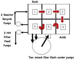
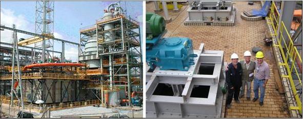
Phosphate rock is fed to the first compartment along with the controlled slurry recycle flow. A horizontal centrifugal pumps operates with variable speed control to effect the reactor recirculation. In the first four compartments fitted with fully open passages between them, the rock is dissolved and a controlled percentage of calcium is precipitated by the action of the sulphate content of the recycle slurry. The fourth compartment overflows to the fifth compartment where sulphuric acid premixed with return acid from the filter is added in a proprietary mixing cone. This mixing cone is designed to operate without the need of regular cleaning. The slurry passes through an underflow to the sixth compartment. Slurry is pumped from the sixth compartment to a proprietary flash cooler. The use of a separate reactor recycle and flash-cooler pumps is based on experience when using blends with phosphate rocks containing large particles of abrasive silica. The filter feed pump feeds the HH belt filter. The gases from the flash cooler go to the vacuum section. The dip-pipe of the flash-cooler return is situated in an external chamber to prevent interference with the agitator of the fifth compartment. In this propose, there is no chance of accidental overflow of slurry from launders as the passages are within the monolithic reactor. Also the gas tightness of the concrete design is superior due to the single concrete roof fitted with two collectors for the off-gases. This minimizes vagrant emissions of off-gas to the environment around the reactors and creates a healthier environment. Access to the agitators is safe on the acid proof tiled roof as can be seen in the photo below.
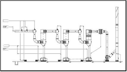
4. THE FILTRATION OFF-GAS SCRUBBING SECTION This section consists of a multi-stage venturi scrubber system with auxiliary variable speed fan. Gases combine with those of the Hemihydrate Off-gas Scrubbing system prior to being routed to the stack. The unit might have two or three stages, but the overall layout is usually similar to the sketch below. 5. THE HEMIHYDRATE FILTRATION SECTION This section consists of two horizontal belt filters operating in parallel. They have two counter-current washes that use as make-up the filtrate from the dihydrate filter. These filters discharge into two independent transformation sections, operating in parallel with the cake being reslurried also by filtrate, from the dihydrate filter. Off-gas from the filter hood goes to the Filtration Off-gas Scrubbing Section.
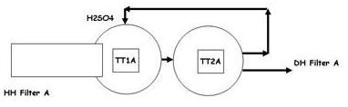
This section comprises two tanks in series, the first with a high powered agitator to re-pulp and blend the HH cake in the \DH slurry and the second with an agitator designed for high flow and low power input. A controlled flow of sulphuric acid is fed to the first tank and a small controlled recycle flow from the second transformation tank to the first. A filter feed pump delivers slurry to the dihydrate filter. Off-gas goes to the Filtration Off-gas Scrubbing Section. 2. THE DIHYDRATE FILTRATION SECTION This section is consists of a horizontal belt filter fitted with two counter-current washes. Hot water from the precondenser can be used for the final wash, prior to cake discharge. The filtrates are returned to the hemihydrate filtration section as wash water and also for sluicing the discharged hemihydrate cake into the transformation section. Off-gas from the filter hood goes to the Filtration Off-gas Scrubbing Section. A split vacuum box on the final cake drainage section can be used, with two separate vacuum systems, to ensure minimum moisture in the discharged dihydrate cake. EVAPORATION UNIT Brief Process Description Introduction:
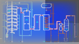
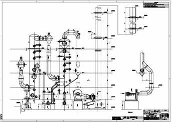
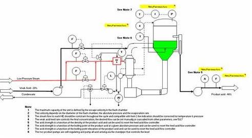
The design basis of an evaporator must define the feed and product strengths. The sizing of the evaporator is based on water evaporated. If the capacity is 900 tpd P₂O₅ when the weak acid has 40% P₂O₅ and the product has 54% P₂O₅, then the water evaporated is 582 tpd H₂O if 3 evaporators are used, each one will evaporate 200 tpd of water; if only two are used, then each one will evaporate 300 tpd of water. Fluosilicic Acid (FSA) is produced in the fluorine recover section which is a co-current absorption tower, operating batchwise to improve recovery. The design comprehends a vacuum evaporator with forced circulation using a graphite tube heat exchanger, an axial-flow pump and a flash chamber. A typical flowsheet is shown above. The recirculation loop is connected to the base of the flash chamber which is fitted with a vortex breaker to prevent cavitation of the axial-flow pump. On the discharge of the axial-flow pump, a filter basket is provided to prevent blockage of the tubes. The heat exchanger is mounted in a vertical position, elevated, preventing boiling in the tubes. Saturated low pressure steam is received from the battery limits and the evaporative capacity of the unit is defined by the flow controller on the steam feed. After passing through the flow control valve, the steam is at the condensing pressure of the heat exchanger and, as such, is slightly superheated. This superheat is removed by the addition of condensate and the temperature is controlled slightly above the saturation temperature of the condensing pressure. The heat exchanger is fitted with a distribution bustle to prevent erosion of the tubes. The velocity of acid in the tubes is selected to minimize scaling and maximize the heat transfer coefficient whilst, preventing erosion of the graphite tubes. The increase in temperature of the acid in each pass is of the order of 3 to 4 °C. Care is taken to ensure that the design of the condensate line to the condensate tank is free-flowing to prevent back-up in the heat exchanger which can cause tube breakage. Also, the level in the condensate tank requires control and interlocks to prevent the same problem. The condensate pump delivers the uncontaminated condensate to the battery limits. A bleed of condensate is used for desuperheating the incoming steam. A sensor detects if the condensate is contaminated with acid and, if so, condensate is routed to drain and the unit shut-down for inspection and repairs. The level in the flash chamber is controlled by an overflow at a height level, that the boiling of the heated acid prior to entering the flash chamber is prevented. Weak acid is received and fed into the acid flow leaving the heat exchanger. A part of the water contained in the mixed acids flashes off on entering the vacuum flash chamber, cooling the acid down to the equilibrium temperature of the desired acid strength at the operating vacuum. The concentrated acid drains via the standpipe overflow to the concentrated acid pump which has auto regulating characteristics. The flashed vapours containing mainly water and fluorine compounds pass through a high-efficiency droplet separator prior to entering the fluorine recovery section. This section uses a small diameter absorption tower in co-current flow. Primary separation of the liquid and gas phases occurs at the base of the tower and residual droplets of FSA are removed in a second high efficiency droplet separator. The residual water vapour passes through a direct contact condenser fed with cooling water prior to entering the vacuum pump. The condenser water is collected in a barometric seal tank which overflows to the battery limits. |
|||||||||||||||||||
|
|
|||||||||||||||||||
| Site Map |